Adding value to an inexpensive steady-light for the bicycle
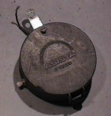 Some years ago, I bought some steady-lights made
by Asista, for my childrens bicyles. I paid about DM 15, (<$10), initially,
which is comparatively inexpensive, for such a device. It's built into
simple plastic box of about 9 cm diameter, with room enough for 4 AA sized
cells, and a 3x5cm printed circuit bord (PCB) located below the batteries. The
box has to be mounted on the generators socket, below the generator. A wire
coming out of the box has to be wired to the generator, and the wire normally
connected to the generator goes to a simple knurled nut on the back of the box
(not visible in the picture to the right). The ground connection goes through
the socket.
Some years ago, I bought some steady-lights made
by Asista, for my childrens bicyles. I paid about DM 15, (<$10), initially,
which is comparatively inexpensive, for such a device. It's built into
simple plastic box of about 9 cm diameter, with room enough for 4 AA sized
cells, and a 3x5cm printed circuit bord (PCB) located below the batteries. The
box has to be mounted on the generators socket, below the generator. A wire
coming out of the box has to be wired to the generator, and the wire normally
connected to the generator goes to a simple knurled nut on the back of the box
(not visible in the picture to the right). The ground connection goes through
the socket.
The device switches the lamp between the generator and the enclosed
batteries. As long as there is some input from the generator, it just lets the
generator feed the lamp. If the generator stops, it supplies current from the
batteries for about 10 to 15 seconds. If that's too short (it usually is), the
cycle can be restarted by just moving the bicycle a little bit.
The advantages are: the device is cheap, very easily mountable, it uses
standard cells and has no switches to be operated. The disadvantage (besides the
relatively primitive design of the box and the connectors) are: the timing isn't
adjustable, and, more important: it doesn't give any light when the bicycle is
slowly moving, and the generator isn't delivering enough current to light the
lamps.
Lately, my children complained about the steady-light "eating" batteries. In
one case, it emptied a set of batteries in less than a week. Instead of trying
to buy a replacement, I decided to build my very own version of the circuit for
switching between generator and batteries, this time. Given that I only barely
managed to get a second Asista steady-light for my other son, when he started to
cycle to school (Asista obviously doesn't build or sell these lights anymore, or
perhaps the local dealers don't carry them, anymore), I didn't have much of a
choice, anyway.
The original Asista PCB uses a condensator to connect the AC current from the
generator to the lamp. My design is a more conservative one. I'm using a
reed-relais to switch the lamp between either the generator or the batteries.
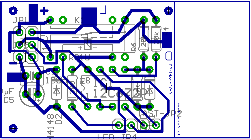
The Asista PCB has a size of about 2,5*5 cm, and snaps nicely into two clamps on
the body of the Asista box. I already had done a PCB design (for a different
kind of steady-light, not yet finished), with a smaller footprint, so I only had
to add another centimeter of empty board space on one side, in order to
get a PCB snuggly fitting into the box.
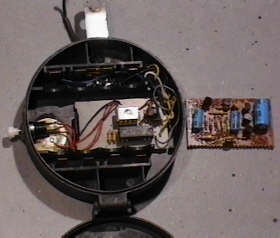 The box, opened. From left to right, we see a button, a
small piezo disk (buzzer), my replacement pcb, and, outside the box, the
original circuit.
The box, opened. From left to right, we see a button, a
small piezo disk (buzzer), my replacement pcb, and, outside the box, the
original circuit.
The original PCB connects the generator to the lamp by a 1000µF/12V capacitor
(polarized!), it's the big blue capacitor on the right.In addition, it contains
two other electrolytic capacitors, five transistors, two ceramic capacitors,
four diodes and six resistors.
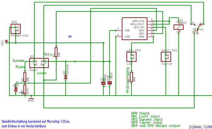
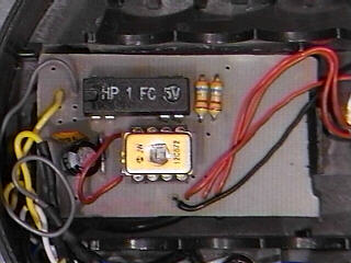 My
circuit is based on a 12C672 processor made by Microchip (a fully functional
computer built into a standard 8 pin plastic dual inline), a 5V reed relais in a
DIL housing, two capacitors, two resistors and a optional diode for protecting
the circuit against reversed batteries.
My
circuit is based on a 12C672 processor made by Microchip (a fully functional
computer built into a standard 8 pin plastic dual inline), a 5V reed relais in a
DIL housing, two capacitors, two resistors and a optional diode for protecting
the circuit against reversed batteries.
Duplicating the original function only needs three of the six available
I/O-pins, so I wired one to the relais output (implementing a simple minded
battery control that way), and added a buzzer and a button (both visible on the
right, on the picture below).
A simple steady-light circuit
Some random remarks
I had to connect two output pins to the reed-relais coil, because the driving
capacity of a single pin isn't enough to reliably drive a changer relais. A
changer needs about twice the current of the simple single contact relais.
JP4 labeled LED is used for sound output via a piezo disc, not for a LED; no
current resistor necessary (replaced by a piece of wire).
D2 isn't necessary, it just short-circuits the power, if the poles are
reversed, accidentally. It's a realtively inexpensive safety measure during
testing.
JP1 isn't really necessary or used. Just like the original PCB, I added some
large rectangles of copper for the main connections, and soldered some of the
wires on the copper (i.e. bottom) side of the PCB. There isn't enough space for
connectors above the board.
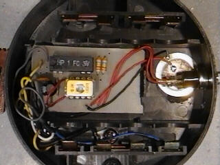
For the same reason, I had to solder the relais without using a socket. Even
without a socket, there is only about 0,5mm space left between the bottom of the
batteries and the top of the relais. I'm a bit unhappy about that, because the
relais actually is the most expensive part of the whole thing.
JP2, the button, doesn't have a pull-up resistor. When using the board with a
(less expensive) 12C508, one would have to be added, in order to make it work.
The 12C672 I'm currently using is more expensive, but has internal pullups (and,
with its 14 bit core, it is supported by the C compiler I'm use for the
firmware).
The voltage divider plus zener diode on the left is overkill. A simple 20k
resistor does just fine.
Printed Circuit Board
Software
Currently, the program just duplicates the original functionality, more or
less. A description of a more sophisticated program (and a report about how well
it worked in real life) will follow in January.
Copyright © 1998 by Wolfgang
Strobl, all rights reserved